- 您现在的位置:买卖IC网 > Sheet目录2006 > LTC2451ITS8#TRPBF (Linear Technology)IC ADC 16BIT DELTA SIG TSOT23-8
LTC2451
16
2451fg
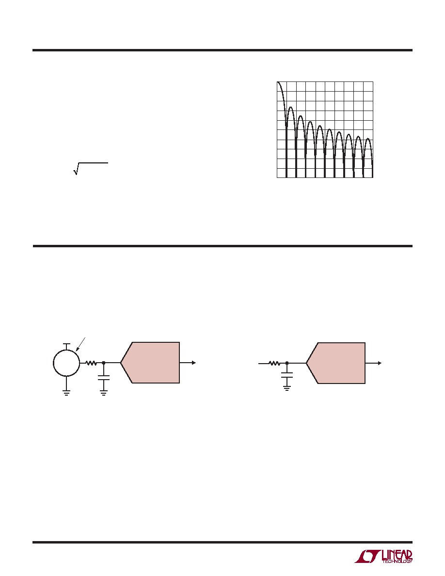
TYPICAL APPLICATIONS
Easy Passive Input
Easy Active Input
LTC2451
100nF
PRECONDITIONED SENSOR
WITH VOLTAGE OUTPUT
1k
V+
GND
VOUT
2451 TA02
LTC2451
100nF
RS < 1k
2451 TA03
Figure 15. LTC2451 Input Signal Attenuation
vs Frequency (Low Frequencies)
INPUT SIGNAL FREQUENCY (Hz)
0
INPUT
SIGNAL
A
TTENUA
TIOIN
(dB)
–20
–10
0
480
2451 F15
–30
–40
–25
–15
–5
–35
–45
–50
120
60
240
180
360 420
540
300
600
For a simple system noise analysis, the input drive cir-
cuit can be modeled as a single-pole equivalent circuit
characterized by a pole location, fi, and a noise spectral
density, ni. If the converter has an unlimited bandwidth,
or at least a bandwidth substantially larger than fi, then
the total noise contribution of the external drive circuit
would be:
Vn = ni p / 2 fi
The total system noise level can then be estimated as
the square root of the sum of (Vn2) and the square of the
LTC2451 noise floor (~2V2).
APPLICATIONS INFORMATION
发布紧急采购,3分钟左右您将得到回复。
相关PDF资料
LTC2452ITS8#TRPBF
IC ADC 16BIT DELTA SIG TSOT23-8
LTC2453ITS8#TRMPBF
IC ADC 16BIT DELTA SIG TSOT23-8
LTC2482IDD#TRPBF
IC ADC 16BIT 10-DFN
LTC2483IDD#TRPBF
IC ADC 16BIT I2C 10-DFN
LTC2485CDD#TRPBF
IC ADC 24BIT I2C 10-DFN
LTC2487CDE#PBF
IC ADC 16BIT DELTA SIG 14-DFN
LTC2492IDE#TRPBF
IC ADC 24BIT DELTA SIG 14-DFN
LTC2493IDE#TRPBF
IC ADC 24BIT DELTA SIG 14-DFN
相关代理商/技术参数
LTC2452CDDB#PBF
制造商:Linear Technology 功能描述:ADC Single Delta-Sigma 60sps 16-bit Serial 8-Pin DFN EP 制造商:Linear Technology 功能描述:Bulk
LTC2452CDDB#TRMPBF
功能描述:IC ADC 16BIT DELTA SIG 8-DFN RoHS:是 类别:集成电路 (IC) >> 数据采集 - 模数转换器 系列:- 产品培训模块:Lead (SnPb) Finish for COTS
Obsolescence Mitigation Program 标准包装:1 系列:- 位数:10 采样率(每秒):357k 数据接口:DSP,MICROWIRE?,QSPI?,串行,SPI? 转换器数目:1 功率耗散(最大):830µW 电压电源:单电源 工作温度:-40°C ~ 85°C 安装类型:表面贴装 封装/外壳:10-WFDFN 裸露焊盘 供应商设备封装:10-TDFN-EP(3x3) 包装:剪切带 (CT) 输入数目和类型:2 个单端,单极;2 个单端,双极;1 个差分,单极;1 个差分,双极 产品目录页面:1396 (CN2011-ZH PDF) 其它名称:MAX1395ETB+TCT
LTC2452CDDB#TRPBF
功能描述:IC ADC 16BIT DELTA SIG 8-DFN RoHS:是 类别:集成电路 (IC) >> 数据采集 - 模数转换器 系列:- 标准包装:2,500 系列:- 位数:16 采样率(每秒):15 数据接口:MICROWIRE?,串行,SPI? 转换器数目:1 功率耗散(最大):480µW 电压电源:单电源 工作温度:-40°C ~ 85°C 安装类型:表面贴装 封装/外壳:38-WFQFN 裸露焊盘 供应商设备封装:38-QFN(5x7) 包装:带卷 (TR) 输入数目和类型:16 个单端,双极;8 个差分,双极 配用:DC1011A-C-ND - BOARD DELTA SIGMA ADC LTC2494
LTC2452CTS8#PBF
制造商:Linear Technology 功能描述:Bulk 制造商:Linear Technology 功能描述:MS-ADC/Delta Sigma, CUT TAPE 16-bit 60Hz SPI Different Ultra-Tiny Delta Sigma ADC
LTC2452CTS8#TRMPBF
功能描述:IC ADC 16BIT DELTA SIG TSOT23-8 RoHS:是 类别:集成电路 (IC) >> 数据采集 - 模数转换器 系列:- 标准包装:1 系列:microPOWER™ 位数:8 采样率(每秒):1M 数据接口:串行,SPI? 转换器数目:1 功率耗散(最大):- 电压电源:模拟和数字 工作温度:-40°C ~ 125°C 安装类型:表面贴装 封装/外壳:24-VFQFN 裸露焊盘 供应商设备封装:24-VQFN 裸露焊盘(4x4) 包装:Digi-Reel® 输入数目和类型:8 个单端,单极 产品目录页面:892 (CN2011-ZH PDF) 其它名称:296-25851-6
LTC2452CTS8#TRPBF
功能描述:IC ADC 16BIT DELTA SIG TSOT23-8 RoHS:是 类别:集成电路 (IC) >> 数据采集 - 模数转换器 系列:- 标准包装:2,500 系列:- 位数:16 采样率(每秒):15 数据接口:MICROWIRE?,串行,SPI? 转换器数目:1 功率耗散(最大):480µW 电压电源:单电源 工作温度:-40°C ~ 85°C 安装类型:表面贴装 封装/外壳:38-WFQFN 裸露焊盘 供应商设备封装:38-QFN(5x7) 包装:带卷 (TR) 输入数目和类型:16 个单端,双极;8 个差分,双极 配用:DC1011A-C-ND - BOARD DELTA SIGMA ADC LTC2494
LTC2452IDDB#PBF
制造商:Linear Technology 功能描述:ADC Single Delta-Sigma 60sps 16-bit Serial 8-Pin DFN EP 制造商:Linear Technology 功能描述:Bulk
LTC2452IDDB#TRMPBF
功能描述:IC ADC 16BIT DELTA SIG 8-DFN RoHS:是 类别:集成电路 (IC) >> 数据采集 - 模数转换器 系列:- 产品培训模块:Lead (SnPb) Finish for COTS
Obsolescence Mitigation Program 标准包装:1 系列:- 位数:10 采样率(每秒):357k 数据接口:DSP,MICROWIRE?,QSPI?,串行,SPI? 转换器数目:1 功率耗散(最大):830µW 电压电源:单电源 工作温度:-40°C ~ 85°C 安装类型:表面贴装 封装/外壳:10-WFDFN 裸露焊盘 供应商设备封装:10-TDFN-EP(3x3) 包装:剪切带 (CT) 输入数目和类型:2 个单端,单极;2 个单端,双极;1 个差分,单极;1 个差分,双极 产品目录页面:1396 (CN2011-ZH PDF) 其它名称:MAX1395ETB+TCT